Marine Lithium Battery Commissioning Checklist
Commission a marine lithium battery system with documented checks for protection, charging, BMS shutdown, monitoring, cable voltage drop and essential services.
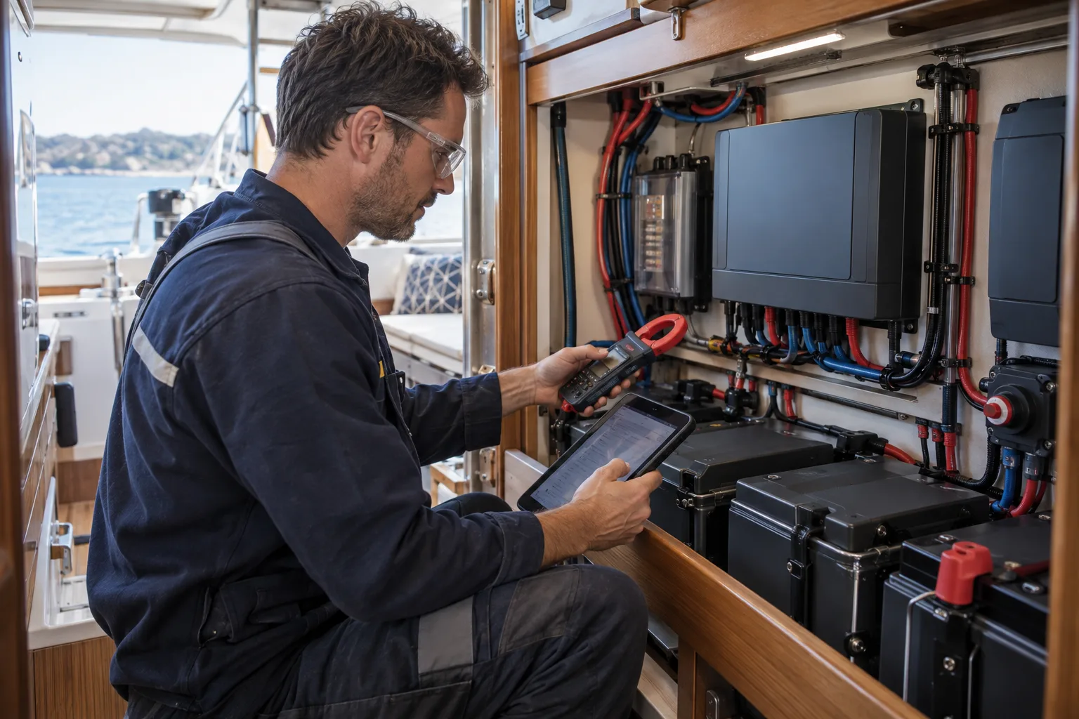
A marine lithium installation is not finished when the final cable is connected. Commissioning is the controlled process of proving that the battery, protection, charging sources, monitoring and loads behave as one system—and recording enough evidence for the owner, electrician, surveyor or future technician to understand what was tested.
This checklist is a planning aid, not a substitute for the current standard, manufacturer instructions or the work of a suitably competent person. The Australian Maritime Safety Authority says lithium-ion batteries should be treated as a battery energy storage system rather than a drop-in replacement and recommends installation and regular inspection by a competent person. See AMSA’s electrical safety guidance.
1. Freeze the installed configuration
Before testing, record the equipment actually installed—not what was originally quoted. Photograph labels and write down model numbers, firmware versions, fuse and breaker ratings, cable sizes, BMS limits, charger profiles and temperature-sensor locations.
Mark every positive and negative connection on an as-built diagram. Include the engine-start battery, emergency parallel arrangement, alternator interface, solar controllers, shore charger, inverter-charger, shunt, busbars, isolators and any always-on circuits. If the diagram does not match the boat, correct it before commissioning continues.
2. Complete a de-energised inspection
With the system isolated using the approved procedure, check mechanical restraint, terminal covers, cable support, bend radius, strain relief, abrasion protection, conductor identification and separation from heat, fuel, water and moving equipment.
Confirm that over-current protection is located and rated according to the design, that the battery can be isolated without improvisation, and that service access does not require leaning tools across live terminals. Look for a clear escape path for heat or gas consistent with the battery manufacturer’s instructions.
3. Prove polarity, voltage and monitoring
Check polarity before closing an isolator. Measure battery and bus voltage with a suitable meter, then compare the reading with the battery monitor and BMS application. A small disagreement should be investigated rather than hidden by immediately recalibrating the display.
Verify that the shunt captures every house-bank current path. Loads or charging sources connected directly to the battery side of the shunt can make state-of-charge estimates look reassuring while energy bypasses the monitor.
4. Test every charging source separately
Commission solar, alternator, shore power and generator charging one source at a time before combining them. Record starting state of charge, voltage, current, temperature, charger stage and sustained output after equipment has warmed up.
Confirm charge-voltage limits, current limits, low-temperature inhibition where required, and the response when the BMS reduces or removes charge permission. An alternator test should include temperature and belt observations at sustained output, not only a brief idle-speed reading. Use the alternator charging calculator to compare measured replacement energy with the vessel’s daily load.
5. Test loads and protection deliberately
Introduce large loads in a planned sequence. Record inverter start-up surge, continuous DC current, voltage at the battery and voltage at the load. Confirm that normal operating current remains within the battery, BMS, cable, connection and protection limits.
Protection tests should follow the equipment manufacturer’s method. Do not create an uncontrolled short circuit or defeat a safety device to see whether it works. Where shutdown behaviour can be tested safely, verify alarms first, then controlled load shedding, then the final protective action.
6. Prove essential-service continuity
The owner should know what remains available after a house-bank or inverter shutdown. Test the intended fallback for engine starting, bilge pumping, navigation lights, steering support, VHF, AIS and position reporting. The correct design depends on the vessel, but the result must be explicit rather than assumed.
Use the essential-services reserve guide and BMS shutdown design guide to document priorities and recovery steps.
Commissioning record to retain aboard
The final handover should include the as-built diagram, equipment schedule, settings export or screenshots, measured voltage-drop results, charge-source results, load-test results, alarm and shutdown observations, unresolved defects, photographs and the date and identity of the person who performed each test.
Commissioning does not prove that the installation will remain safe forever. Add terminal, wiring, battery and charging checks to the vessel’s maintenance plan. AMSA reports that electrical installations and test records have repeatedly appeared among common domestic commercial vessel inspection issues, making the record part of the safety system rather than paperwork to discard.
- 01DesignLoads, voltage and failure paths
- 02ControlCharging limits and BMS logic
- 03ProtectionFuses, isolation and conductors
- 04EnvironmentHeat, water, salt and restraint
- 05ProofCommissioning and records